CONFIGURANDO SWITCHS QUANTA COM METRO ETHERNET E DOUBLE VLAN (Qinq) on FASTPATH

Share Button

English Title: CONFIGURING QUANTA SWITCH WITH METRO ETHERNET AND DOUBLE VLAN (QinQ) on FASTPATH

Este artigo demostra como configurar switchs quanta rodando o firmware fastpath.
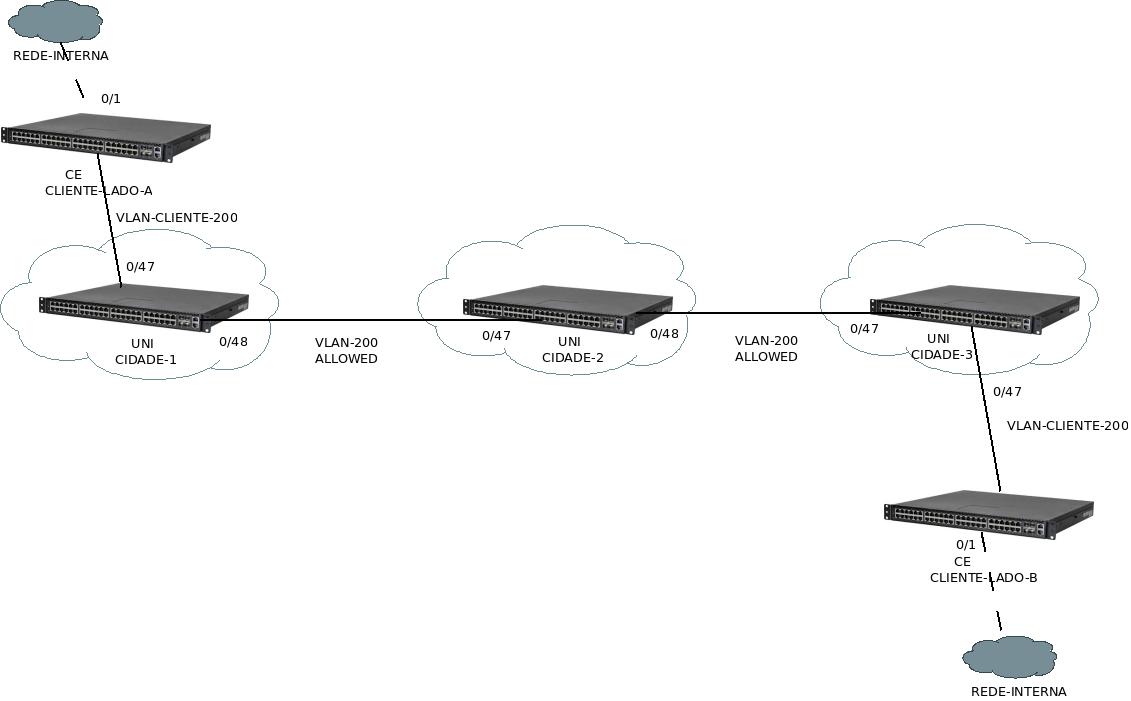
Vamos ao cenário.

Neste cenário utilizaremos 3 switch cada um representando uma cidade atendidas pela rede metro e entre essas cidades forneceremos a um cliente uma LAN-to-LAN usando a rede metro.

Este cenário permitira o cliente usar um trafego sem marcação de VLAN (untagged) e a marcação de uma ou mais VLANs (tagged), deixando essas VLANs que são marcadas pelo cliente invisíveis para a rede metro, tornando a rede mais flexível para o cliente sem que a operadora se preocupe em quais vlan-ids ou segmentação o cliente esta usando ou necessitará futuramente.

NOMENCLATURAS
UNI – User Network Interface
CE – Customer Equipment

rede-metro

CONFIGURAÇÕES DO SWITCH DA CIDADE 1

(SW-CIDADE-1) # vlan database
(SW-CIDADE-1) (Vlan)# 200
(SW-CIDADE-1) #configure
(SW-CIDADE-1) (Config)#interface 0/47
(SW-CIDADE-1) (Interface 0/1)#vlan participation include 200
(SW-CIDADE-1) (Interface 0/1)#vlan tagging 200
(SW-CIDADE-1) (Interface 0/1)#mode dvlan-tunnel
(SW-CIDADE-1) (Config)#interface 0/48
(SW-CIDADE-1) (Interface 0/1)#vlan participation include 200
(SW-CIDADE-1) (Interface 0/1)#vlan tagging 200
(SW-CIDADE-1) (Interface 0/1)#mode dvlan-tunnel

CONFIGURAÇÕES DO SWITCH DA CIDADE 2

(SW-CIDADE-2) # vlan database
(SW-CIDADE-2) (Vlan)# 200
(SW-CIDADE-2) #configure
(SW-CIDADE-2) (Config)#interface 0/47
(SW-CIDADE-2) (Interface 0/1)#vlan participation include 200
(SW-CIDADE-2) (Interface 0/1)#vlan tagging 200
(SW-CIDADE-2) (Interface 0/1)#mode dvlan-tunnel
(SW-CIDADE-2) (Config)#interface 0/48
(SW-CIDADE-2) (Interface 0/1)#vlan participation include 200
(SW-CIDADE-2) (Interface 0/1)#vlan tagging 200
(SW-CIDADE-2) (Interface 0/1)#mode dvlan-tunnel

CONFIGURAÇÕES DO SWITCH DA CIDADE 3

(SW-CIDADE-3) # vlan database
(SW-CIDADE-3) (Vlan)# 200
(SW-CIDADE-3) #configure
(SW-CIDADE-3) (Config)#interface 0/47
(SW-CIDADE-3) (Interface 0/1)#vlan participation include 200
(SW-CIDADE-3) (Interface 0/1)#vlan tagging 200
(SW-CIDADE-3) (Interface 0/1)#mode dvlan-tunnel
(SW-CIDADE-3) (Config)#interface 0/48
(SW-CIDADE-3) (Interface 0/1)#vlan participation include 200
(SW-CIDADE-3) (Interface 0/1)#vlan tagging 200
(SW-CIDADE-3) (Interface 0/1)#mode dvlan-tunnel

CONFIGURAÇÕES DO SWITCH DO CLIENTE LADO A

(SW-CLIENTE-LADO-A) # vlan database
(SW-CLIENTE-LADO-A) (Vlan)# 200
(SW-CLIENTE-LADO-A) #configure
(SW-CLIENTE-LADO-A) (Config)#interface 0/1
(SW-CLIENTE-LADO-A) (Interface 0/1)#vlan participation include 200
(SW-CLIENTE-LADO-A) (Interface 0/1)#vlan pvid 200
(SW-CLIENTE-LADO-A) (Config)#interface 0/47
(SW-CLIENTE-LADO-A) (Interface 0/1)#vlan participation include 200
(SW-CLIENTE-LADO-A) (Interface 0/1)#vlan tagging 200
(SW-CLIENTE-LADO-A) (Interface 0/1)#mode dvlan-tunnel

CONFIGURAÇÕES DO SWITCH DO CLIENTE LADO B

(SW-CLIENTE-LADO-B) # vlan database
(SW-CLIENTE-LADO-B) (Vlan)# 200
(SW-CLIENTE-LADO-B) #configure
(SW-CLIENTE-LADO-B) (Config)#interface 0/1
(SW-CLIENTE-LADO-B) (Interface 0/1)#vlan participation include 200
(SW-CLIENTE-LADO-B) (Interface 0/1)#vlan pvid 200
(SW-CLIENTE-LADO-B) (Config)#interface 0/47
(SW-CLIENTE-LADO-B) (Interface 0/1)#vlan participation include 200
(SW-CLIENTE-LADO-B) (Interface 0/1)#vlan tagging 200
(SW-CLIENTE-LADO-B) (Interface 0/1)#mode dvlan-tunnel


CONFIGURANDO SWITCHS QUANTA (FASTPATH)

Share Button

HP, English Title: Configuring quanta switchs

Neste post irei demostrar as principais configurações de switchs QUANTA com firmware FASTPATH

A primeira diferença entre o switch quanta e a maioria dos switchs do mercado é que nessa versão de firmware FASTPATH algumas das configurações básicas são feitas em modo enable e não em modo configure como de costume.

Vamos ao que interessa.

Configurando o name do router

set prompt "SW-01-LOCAL"

Setando o password de enable

enable passwd encrypted minhasenha

Configurando IP de gerencia
Iremos configurar o IP 192.168.0.10/24 com o gateway 192.168.0.1 na vlan de gerencia 10

network protocol none
network parms 192.168.0.10 255.255.255.0 192.168.0.1
network mgmt_vlan 10

Criando Vlans

vlan database
vlan 10,20,30

Nomeando as Vlans

vlan name 10 "VLAN-10" 
vlan name 20 "VLAN-20" 
vlan name 30 "VLAN-30" 

Configurando snmp
Obs. Note que daqui para frente devemos estar em modo configure para realizar as próximas configurações

snmp-server sysname "SW-01-LOCAL"
snmp-server location "MEU-LOCAL"
snmp-server contact "MEU_CONTATO"

Setando usuário e senha para acesso telnet e WEB

users passwd "admin" encrypted minhasenha

Desabilitando o spanning-tree de todo o switch

no spanning-tree

Configurando uma porta como acesss da vlan 10 (untagged)

interface 0/1
description 'DESCRIÇÃO'
no spanning-tree port mode
vlan pvid 10
vlan participation include 10
exit 

Configurando uma porta para repassar a VLAN (Trunk / General) para permitir a passagem das vlans 10 e 20

interface 0/1
description 'DESCRIÇÃO'
no spanning-tree port mode
vlan acceptframe vlanonly
vlan participation include 10,20
vlan tagging 10,20
exit 

Configurando port-channel

Criando o port channel

port-channel system priority 1
port-channel PORT-CHANNEL1

Habilitando o LACP dinâmico

interface 1/2
no port-channel static

Checando qual a interface do port channel

show port-channel all

                                                                         
Log.       Channel            Adm.      Mbr    Device/       Port      Port
Intf        Name        Link  Mode Type Ports  Timeout       Speed     Active
------ --------------- ------ ---- ---- ------ ------------- --------- -------
3/1    PORT-CHANNEL1     Up     En.  Dyn. 0/1    actor/long    Auto      True   
                                               partner/long  
                                        0/2    actor/long    Auto      true  
                                               partner/long  

Neste caso como é o primeiro port channel o nome da interface para ele é 3/1 caso existam mais quem um port-channel ele terá o nome das próximas interfaces, como 3/2..3/3…..

Setando o tipo de loadbalance
Esse switch como é L2 e L3 possui vária formas de ser configurado o LB como:
1 Src MAC, VLAN, EType, incoming port
2 Dest MAC, VLAN, EType, incoming port
3 Src/Dest MAC, VLAN, EType, incoming port
4 Src IP and Src TCP/UDP Port fields
5 Dest IP and Dest TCP/UDP Port fields
6 Src/Dest IP and TCP/UDP Port fields

Nesse caso configurarei com a opção 6 – Src/Dest IP and TCP/UDP Port fields

port-channel load-balance 6 3/1

Adicionando interfaces ao port-channel

interface 0/1
addport 3/1
exit 
interface 0/2
addport 3/1
exit